Pcm modulation and demodulation circuit diagram Pulse oximetry modular oximeter diagram block typical solution adi patient monitors functional jotrin belows Ultrasound block principle pulse scanning apparatus
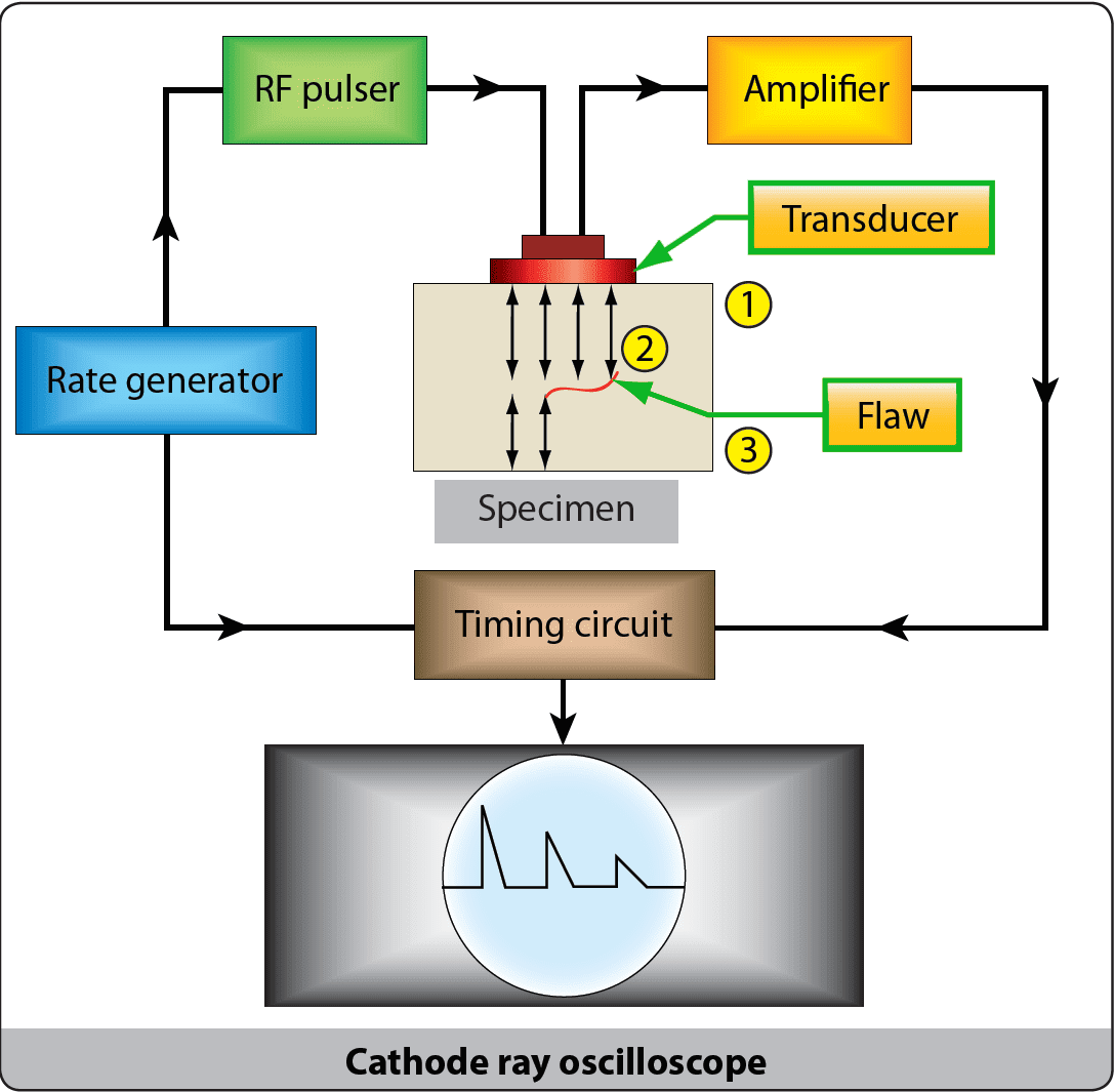
2.13: Pulse-echo technique: schematic electronic setup for the
Diagram block oximeter pulse ppt powerpoint presentation work de2 luz phong altera board Pcm (pulse code modulation) Instrumentation echo ultrasound chapter3 beam
Diagram block ultrasound system dimensional echocardiographic two receive basic imaging optimizing transmit essential generate components required figure
Optimizing two-dimensional echocardiographic imagingWelcome to worltech. (pdf) pulse-echo field distribution measurement technique for highTypical modular pulse oximetry solution in adi patient monitors.
Diagram block pcm system modulation pulse code transmission transmitter path signal receiver electronicscoach regenerative figure disadvantages sampling advantages definition effectsPulse echo diagram block method time figure Echo shaded represents niBlock diagram for pulse/echo velocity measurement system..

Block diagram of the echo-pulse method velocity meter: 1...
What is pulse code modulation (pcm)? definition, block diagramPulse ultrasonic technique velocity delay The pulse-echo principle[diagram] blok diagram pulse oximeter.
Pulse amplitude modulation: sampling techniques, circuit, block diagramSchematic diagram of pulse-echo technique for measuring ultrasonic (a) basic pulse-echo system, (b) typical pulse-echo decay patternPulse amplitude demodulation circuit diagram.

2.13: pulse-echo technique: schematic electronic setup for the
Modulation pulse pcmBlock diagram for the experimental set up: pulse-echo technique (a) the pulse-echo system and experimental setup. the shaded boxNondestructive inspection/testing (part 2).
Pulse modulationBlock diagram of the ultrasound pulse-echo technique using (a Radar pulse basic system systems doppler displayModulation amplitude pam modulated types signals byjus message clear noise.

Pulse echo response – onscale
Block diagram of the echo system.Pcm (pulse code modulation) Pulse code modulation(pcm) block diagram, working principleUltrasound scanning techniques as applied in medical imaging.
Block diagram of designed pulse-echo setup with pulser-receiver modulePulse echo response onscale [diagram] leg pulses diagramPulse code modulation.
(a) block diagram and (b) photo of the pulse-echo response measurement
Pulse-doppler radar systemDiagram block technique ultrasonic echo testing system imaging concrete inspection advantages online pic ndt article Block pulse inspectionEcho pulse decay.
Pulse ultrasound frequency .


Pulse Amplitude Modulation: Sampling Techniques, Circuit, Block Diagram

(PDF) Pulse-echo field distribution measurement technique for high

The Pulse-Echo Principle - YouTube

Optimizing Two-Dimensional Echocardiographic Imaging | Thoracic Key
![[DIAGRAM] Leg Pulses Diagram - MYDIAGRAM.ONLINE](https://i2.wp.com/www.researchgate.net/profile/Asral_Jambek/publication/312325893/figure/fig1/AS:467386580115456@1488445052150/Block-diagram-of-Pulse-Oximeter-system-1.png)
[DIAGRAM] Leg Pulses Diagram - MYDIAGRAM.ONLINE

U | Radiology Key

Schematic diagram of pulse-echo technique for measuring ultrasonic